FORMULA SAE OUTBOARD DRIVE V4 / 2026

OUTBOARD DRIVE.
ENGINEERED AS A SYSTEM.

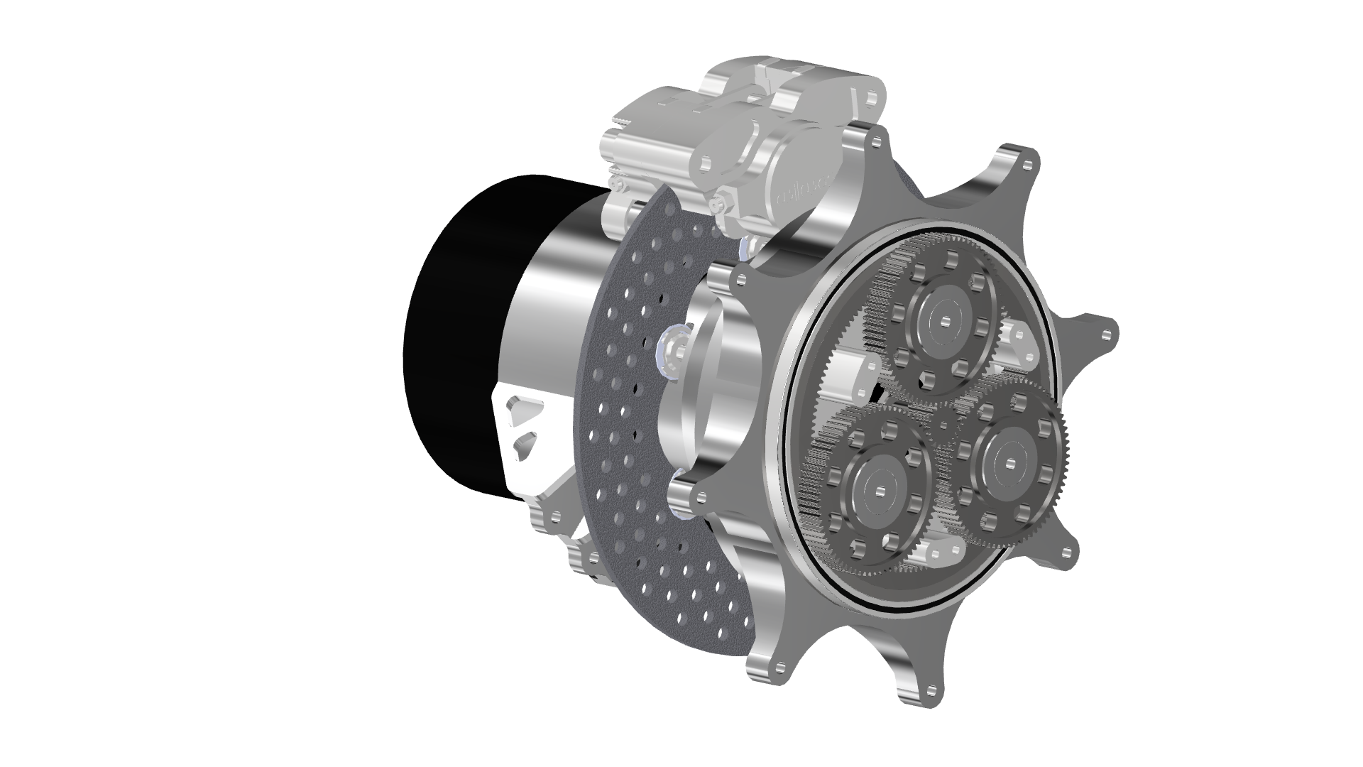
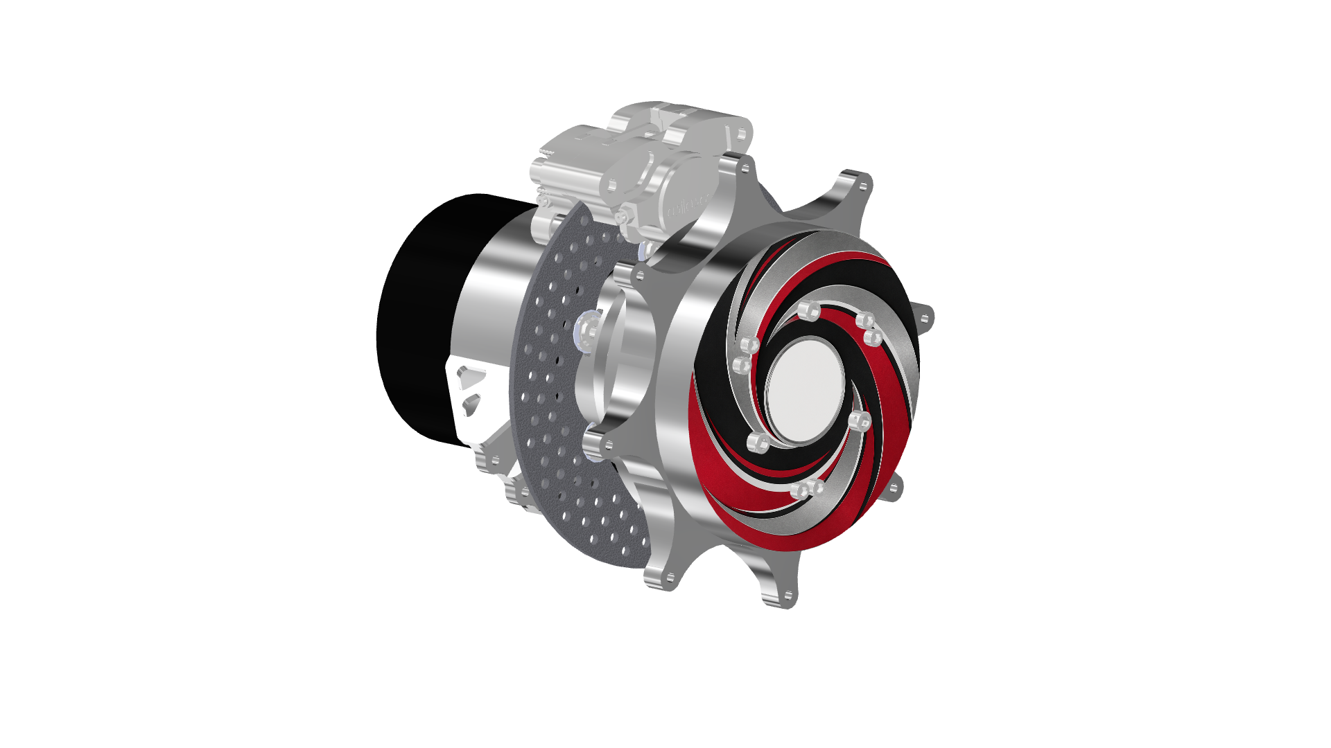
A compact, coaxial drivetrain designed to package the motor and compound planetary gearbox inside the wheel envelope—then automate the path from requirements and optimization to a buildable CAD assembly.

~3 INGEARBOX
THICKNESS TARGET
~8 INPACKAGE
DIAMETER TARGET
64VALID
CONFIGURATIONS
100+CALCULATED
OUTPUTS
01 / CONFIGURATION EXPLORER

COMPARE 64 VALID DESIGNS

Move the configuration slider and switch views to compare automatically generated Inventor assemblies and their key design values.

AUTOMATED INVENTOR OUTPUT
CONFIGURATION 14 / 64
VIEW 1 / 5
LOADING COMBINED CAD VIDEO
AUTOMATED CAD RENDER
CONFIG 14 · VIEW 1 · 1× SPEED
CONFIGURATION14
0116324864
02 / AUTOMATED CAD OUTPUTS

INSPECT THE MECHANICAL SYSTEM

Static comparison, disassembly, exploded inspection, and operating motion—all generated from the same parametric Inventor assembly.

LOADING CONFIGURATION SNAPSHOT
CONFIG 14 · VIEW 1
SELECTED OUTPUT

CONFIGURATION

A still inspection frame from the active configuration and camera view. The image updates with the design selector above.

STATIC SNAPSHOT5 VIEWS64 DESIGNS
03 / iLOGIC CONTROL MODES

ONE MODEL.
THREE PURPOSE-BUILT STATES.

These are rule-driven states of the same parametric assembly, allowing the design to move from system communication to detailed gear inspection and manufacturing preparation.

04 / END-TO-END AUTOMATION

FROM REQUIREMENTS TO HARDWARE

The system searches the design space, stores valid results, rebuilds the CAD assembly, and produces consistent engineering outputs with minimal manual redesign.

01Optimize

MATLAB

Searches thousands of tooth-count and module combinations while enforcing ratio, packaging, spacing, geometry, and hunting-ratio constraints.

02Structure

EXCEL

Stores every valid configuration and more than 100 calculated outputs in a controlled data source for the CAD model.

03Generate

INVENTOR + iLOGIC

Rebuilds gears, housing, bearings, interfaces, clearances, and display modes from the selected configuration.

04Communicate

INTEGRATED OUTPUT

Produces repeatable configuration views, mechanical animations, and data-driven comparisons for engineering review.

V1
CONCEPT

Proved the ring-output architecture and wheel-package feasibility.

V2
ARCHITECTURE

Reversed the compound stages to explore a stronger layout.

V3
INTEGRATION

Added upright, bearing, brake, wheel, and structural interfaces.

V4
AUTOMATION

Unified master parameters, iLogic behavior, manufacturing detail, and configuration control.

05 / PARAMETRIC MECHANICAL SYSTEM

ONE CONFIGURATION.
THE WHOLE DRIVE.

One selection updates the gearbox definition, housing, bearing locations, clearances, and downstream engineering data.

ACTIVE CONFIGURATION14

A single selector changes the design definition.

01 / DRIVE9

INPUT PARAMETERS

Automatically remapped when the configuration number changes.

02 / CONTROL3

CONTROL FEATURES

Coordinate the rule-driven behavior of the parametric model.

03 / RESOLVE100+

OUTPUT PARAMETERS

Recalculated across geometry, performance, validation, and documentation.

INVENTOR AUTOMATION

iLOGIC RULE NETWORK

The configuration inputs propagate through a substantial iLogic system, rebuilding the gearbox definition and its downstream model state without manually editing individual parts.

CONFIG-DRIVENRULE-BASEDASSEMBLY-WIDE
SUPPLY-CHAIN INTEGRATION

SKF DATABASE + MATLAB

MATLAB searches the SKF database for the design-specific purchased component and pulls its dimensions into the calculation chain. In this study, it is the only ordered part that changes between configurations.

PART LOOKUPDIMENSION PULLORDER-READY
MECHANICAL INTEGRATION

ONE COAXIAL PACKAGE

The motor, compound planetary stages, ring output, bearings, brake interfaces, upright, and wheel mounting share one centerline to eliminate conventional driveshafts and reduce packaging volume.

OUTBOARD DRIVEIN-WHEEL PACKAGESYSTEM-LEVEL CAD
06 / NEXT ITERATION

CLOSE THE
ENGINEERING LOOP.

The current workflow automates generation, filtering, data transfer, CAD updates, and visualization. The next phase will automatically simplify each valid model, run FEA, compare performance, and feed results back into the optimization.

FEA / FEMAUTOMATED TESTINGMULTI-OBJECTIVE OPTIMIZATION
01GENERATE
02BUILD
03SIMULATE
04MEASURE
05OPTIMIZE
CLOSEDLOOPDESIGN SYSTEM